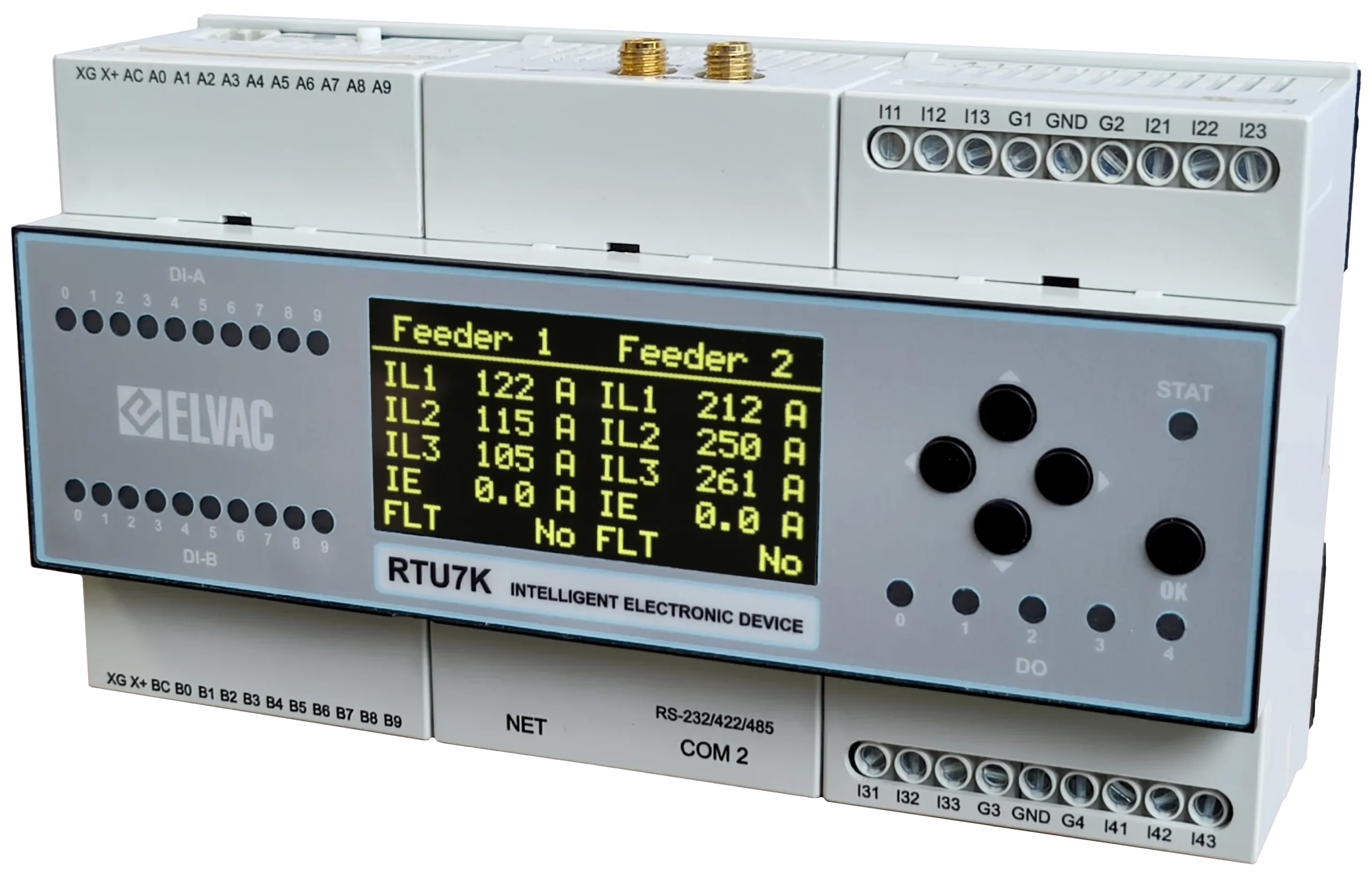
RTU7K – 2nd Generation of Compact Size Control and Communication Unit
Unit Description
The second generation of RTU7K builds on the proven design of the previous generation of compact units and brings much more performance needed to implement modern functions used in the energy sector, such as the need for secure communication or the use of sophisticated communication protocols. In addition, it brings improvements in many other parameters, which expands the possibilities of use and facilitates the installation and maintenance of systems. Thanks to the compact design, it also offers a cost-effective solution for applications for which these units are tailored.
Typical Applications
- Fault passage indicator for up to four MV feeders:
- 4 x 3-phase current measurement,
- located usually in secondary substations
- 3-phase MV feeder monitoring, control and protection:
- one 3-phase voltage and current measurement,
- located usually in feeders in substations, in pole mounted reclosers or in load break switches (sectionalizers).
- 3-phase monitoring, control and protection of renewable energy sources:
- one 3-phase voltage and current measurement,
- located usually in hydroelectric, wind, photovoltaic, combined heat and power, biogas power plants.
- 3-phase monitoring, control and protection of SMART network nodes:
- one 3-phase voltage and current measurement,
- located usually in battery storage, car chargers, balancing services.
Communication Protocols and Services
IEC 60870-5-101
IEC 60870-5-103
IEC 60870-5-104
IEC 61850 (GOOSE, MMS)
DNP3.0
Modbus TCP/RTU
DLMS
OPC UA
SQL
HTTPS
HioCom2
SNMP
IPSec
OpenVPN
Firewall
NAT
PRP/HSR
NTP
Syslog
SSH
SCEP
RADIUS
RBAC
IEC 62351-3
Basic Features
- 3-phase voltage and current measurement on medium voltage feeders, see the HW variants in the tables below,
- fault indication according to ANSI standards, see the tables below,
- network disturbance records in format COMTRADE,
- 20 × DI, dry or wet contact, periodical evaluation and filtering of input changes,
- 5 × DO (relay), SW and HW protection against accidental switching,
- 1 x RS-232/422/485, 1 x Ethernet LAN 10/100 Mbps, 1 x LTE modem,
- power supply voltage 10 ÷ 60 V DC,
- battery charger – automatic detection of connected battery 12 or 24 V, periodical testing of battery status (capacity), power supply voltage should be higher than battery voltage,
- HMI – operating values display, local control and setup via buttons,
- secure communication according to IEC 62351-3 (TLS),
- web configuration interface HTTP/HTTPS
- digitally signed OS and FW,
- SQL database data storage support,
- user programmable logic based on standard IEC 61131-3,
- internal thermal sensor, embedded RTC,
- DIN rail or panel mounting.